
Moisture in a Transformer
Where does moisture occur in a transformer?
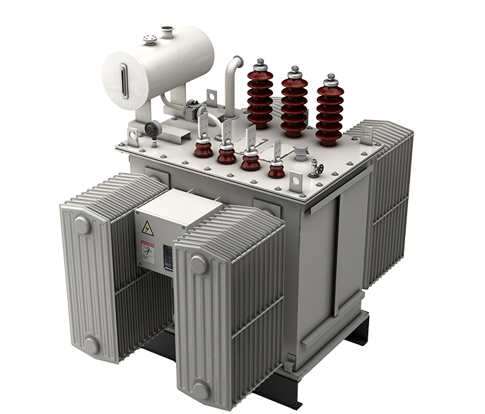
Moisture occurs in the oil and paper insulation systems of a transformer. Moisture is a significant concern for power transformers and can lead to unexpected failure of equipment and unplanned outages. Excessive moisture in the oil of a transformer reduces the oil’s dielectric strength. This introduces the opportunity for flashover and arcing.

What causes moisture inside a transformer?
- Solid insulation inside the transformer – both paper and pressboard; as solid insulation ages, depolymerization of paper generates moisture
- Gaskets deteriorated by aging or improper installation provides a “two-way path” for oil to egress and air and moisture to ingress from the environment
- Broken conservator bags and non-functioning nitrogen gas blanket systems also allow ingress of air and moisture into the system
What is “bubbling” or “bubble evolution”?
Bubbling from the conductor paper insulation happens when the temperature of the conductor is high and the paper wrapped around the conductor is sufficiently wet. In this situation, water vapor bubbles are created in the voids of the paper. These bubbles tend to rise and accumulate on the surfaces of the paper. Thereby reducing the dielectric withstand between turns and sections of the winding. This can cause a turn-to-turn failure (arcing) which can result in a catastrophic failure of the transformer.
Transformer Insulation Moisture Monitoring
How to manage moisture in a transformer?
Management of moisture within a transformer is critical to aging, reliability, performance, and safety. It is important to know the amount of moisture dissolved in the oil. The dielectric strength diminishes as relative saturation increases.
Processing the oil to remove moisture and contaminants will aid in returning the oil to a higher dielectric strength for better performance. While this process removes moisture from the oil, it does not extract moisture from the insulating paper. So drying the oil will have only short term benefits. The important measurement is the % Relative Saturation of the oil.
The acceptable amount of moisture is dependent on temperature, the chemical composition of the oil, and the aging level of the oil. Moisture sensors and monitors are a continuous way to manage moisture of both insulation system components.
In practice, only the relative saturation of moisture in oil can be measured and the moisture in paper must be inferred from it, based on the water absorption characteristics of both oil and paper and time taken for the migration characteristics of water between them under variable temperature conditions.

Karl Fischer Titration Test
Moisture exists in three states: dissolved, bound, and free water. Dissolved moisture is free to move between oil and paper. Bound moisture is attached to acid, fibrous particles, dust, etc. The Karl Fischer Titration test measures all three but cannot differentiate dissolved from bound water. Most utilities employ a schedule for oil sampling and subject the insulating fluid to dissolved gas analysis and moisture content testing. The Karl Fischer Titration test measures the absolute moisture content in the oil and reports the Parts Per Million content.
KF titration is excellent for precise ppm quantification in a clean, controlled lab, but in transformers:
- It does not represent the real-time operating risk (no %RS, no paper insight).
- It is highly sensitive to sampling and oil condition.
- That’s why %RS (online moisture-in-oil probes) is more diagnostic.
PPM will tell you how many water molecules are in the oil. %RS will tell you whether the oil-paper system is at risk of free water, dielectric failure, and moisture migration. That is why many modern standards and monitoring practices are shifting focus from PPM to %RS.
PPM and %RS Comparison Table
| Aspect | PPM (mg/kg in oil) | % Relative Saturation (%RS) |
| Definition | Absolute amount of water dissolved in oil | Ratio of actual water content to oil’s saturation limit at given temperature |
| Temperature Sensitivity | Strongly affected but not corrected for → misleading if temperature not reported | Automatically accounts for oil temperature & solubility curve |
| Risk Indicator | No direct link to risk of free water or breakdown | Direct measure of proximity to free water formation (100% = free water) |
| Comparability Across Oil Types | Misleading, since esters vs mineral oils have vastly different ppm ranges | Normalized → can compare between different oil types |
| Relation to Paper Moisture | Cannot be used directly in partition models | Direct driver for partition equilibrium (oil ↔ paper exchange) |
| Trending & Monitoring | Lab samples only; trends affected by sampling & ambient temperature | Online sensors measure %RS → real-time %RS trending |
| Decision-Making Value | Raw number, requires interpretation with temperature curves | Directly actionable for risk management (drying, load, monitoring actions) |
| Standards Alignment | Older practice (ppm limits) | Supported by IEC 60422 & CIGRÉ models using %RS curves |
Why are moisture probes (%RS) still a niche?
%RS of moisture in transformer oil is a niche diagnostic parameter compared to conventional ppm-based moisture measurements. Unlike absolute moisture content, %RS accounts for oil type and temperature, providing a more accurate indicator of insulation equilibrium and bubble inception risk. Despite its technical advantages, %RS remains specialized due to non-integration in standards/guides, the need for contextual interpretation, low awareness among field engineers, and its primary adoption in online monitoring systems rather than traditional offline sampling. Consequently, %RS is valued predominantly by specialists in transformer condition monitoring and advanced diagnostics.
Temperature sensors are standard in transformers: widely referenced in IEC and IEEE standards because they are easy to install, low-cost, and provide immediate insight into insulation stress and loading limits. A comparison between temperature and moisture reveals that the main issue is non-integration in standards/guides!
Temperature and Moisture Comparison Table
| Temperature Sensors | Moisture Sensors | |
| Sensor technology | Mature (RTDs, thermocouples, fiber optics). | Maturing (capacitive, polymer, etc). |
| Reliability | High: decades of proven field use. | Moderate: calibration drift and not being used for decades! |
| Standardization | Fully embedded in IEC/IEEE loading guides (e.g., IEEE C57.91). | Partial: CIGRE guides (e.g., 349, 741) but no widely enforced online thresholds. |
| Cost | Low | Higher |
| Integration | Directly used in protection, SCADA, and asset life models. | Usually standalone or part of advanced monitoring systems. |
| User confidence | Very high: considered essential for all transformers. | Mixed: many prefer offline Karl Fischer and lab tests. |
| Adoption | Universal (all power transformers). | Niche (critical units, renewables, BESS, or high cyclic loading). |
| Value perception | “Must-have” enables overloading, life calculation, alarms. | “Nice-to-have” mainly for condition-based monitoring and moisture risk mitigation. |
Dual Moisture Probes
Dual moisture probes provide redundancy and cross-checking to ensure reliable data. By measuring at different oil levels, they capture moisture gradients inside the tank and offer a more representative picture of insulation condition. This dual input also strengthens equilibrium models, enabling more accurate estimation of paper moisture content and long-term asset health.
Always specify Dual %RS probes = higher reliability + better spatial coverage + early warning.
Single and Dual %RS Sensor Comparison Table
| Single %RS Sensor | Dual %RS Sensor | |
| Measurement of %RS/Temperature at sensor location | ✓ | ✓ |
| Estimation of Water Content in Oil (WCO) @sensor location | ✓ | ✓ |
| Accurate determination of WCO in cooling loop | ✗ | ✓ |
| WCO forecasting: WCO = f(T1,T2) | ✗ | ✓ |
| Simultaneous assessment of Water Content in Paper (WCP) at top & bottom oil | ✗ | ✓ |
| Simultaneous assessment of cooling efficiency and paper dryness during Factory Acceptance Test (FAT) | ✗ | ✓ |
| Determination of dry-out end points and filter changeover | ✗ | ✓ |
| Redundancy and sensor drift detection | ✗ | ✓ |
Hidden Moisture Risks in Hot Spare Transformers

Ensuring True Moisture Resilience
Cold spare transformers receive attention in asset management strategies due to its well-recognized risks. Hot spare transformers, which are energized but unloaded, have underestimated risks that frequently go unnoticed. With no load, the oil circulation is minimal, creating critical moisture dynamics issues. For instance, 20 ppm oil moisture may correspond to ~25% RS at 35 °C but exceed >40% RS at 20 °C, which is dangerously close to insulation breakdown and voltage stress thresholds.
Hot spares typically lack online monitoring systems because they’re perceived as low-risk and idle assets, creating a diagnostic blind spot where hidden degradation can develop undetected until the unit is urgently needed. The industry’s false confidence in hot spares as “ready insurance” stems from assuming rather than assuring their operational health.
Effective mitigation practices equip the asset with basic online relative saturation or moisture-in-oil sensors, alarm for unloaded duty cycles, and periodically cycling pumps or applying controlled loads to normalize thermal stress patterns. Hot spare transformers need online monitoring systems to maintain readiness for instant power transfer demands. Grid resilience must include ongoing verification of backup equipment condition to ensure its reliability and readiness. Learn more in our white paper: The Hidden Weakness of Hot Spare Transformers.
Introducing the E3 Transformer Monitor
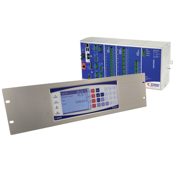
Dynamic Ratings’ E3 Transformer Monitor integrates moisture sensor data and other calculated parameters as part of the moisture management model. Measured values include moisture content in oil in terms of percentage relative saturation, bubble evolution, temperature at the moisture sensor’s location, top oil temperature of the transformer, load current measured on the winding of interest and bottom oil temperature of the transformer.