
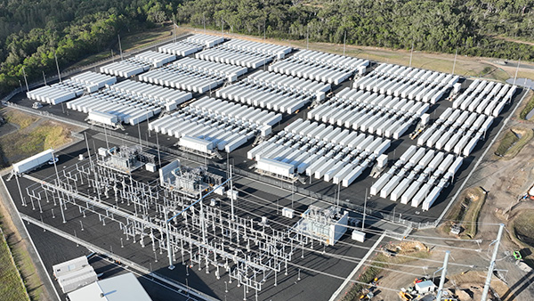
Battery energy storage systems are changing how the transformers that serve them operate, and most monitoring strategies have not caught up. The transformer at a BESS site is often the main grid step-up (GSU) unit that interfaces the storage system with the wider network. It now absorbs a duty cycle unlike anything traditional substation or industrial transformers were built for.
As solar and wind penetration climbs, grid operators lean on battery energy storage systems (BESS) for frequency regulation, ramp rate control, renewable firming, and voltage support. Meeting those demands means the transformer can swing from full charge to full discharge, and back again, several times in a single day. That rapid, bidirectional duty introduces thermal cycling, harmonic rich currents, and fast ramp rates that most transformer designs never anticipated.
That mismatch between traditional transformer duty and modern BESS operation is exactly why condition monitoring for BESS transformers has become such an urgent conversation across the industry. This article breaks down why these transformers carry a fundamentally different stress profile, which monitoring technologies actually close the visibility gap, and what a truly complete monitoring strategy needs to cover.
Why Transformers at BESS Sites Don’t Behave Like Conventional Units
Traditional power transformers were designed around a load that changes gradually and thermal behavior that stays smooth. A GSU transformer serving a BESS breaks that assumption in nearly every direction at once.
The first and most consequential difference is rapid thermal cycling. The same transformer may charge and discharge several times within a single day, repeatedly heating and cooling the winding insulation. Over time, that repetition drives mechanical fatigue in the insulation and redistributes moisture between the paper and the oil. This accelerates the loss of the paper’s degree of polymerization (DP), which is the key measurement that defines a transformer’s remaining lifespan.
Harmonics, Bidirectional Flow and Fast Ramp Rates
While rapid thermal cycling wears on the GSU transformer’s insulation, harmonic exposure drives that same risk through temperature instead. BESS relies on inverter-based power conversion systems. This exposes the transformer to harmonic rich currents that generate eddy current losses and localized, non-uniform heating that a standard hotspot temperature reading may never fully capture.
Bidirectional power flow compounds the challenge further. Since charging imports power and discharging exports it back to the grid, and fast ramp rates can push a transformer from near zero to full output within seconds, the resulting duty cycle stresses insulation, cooling systems, and mechanical structure all at once. Frequent participation in frequency regulation and fault ride through adds repeated short duration electrical events on top of all of it.
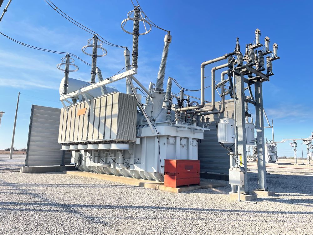
None of these stresses are entirely new to transformer engineering. What’s new is how often and how aggressively they occur together, which is precisely why continuous condition monitoring has become so valuable in Battery Energy Storage Systems.
Thermal and Moisture Monitoring: Seeing What Traditional Sensors Miss
Traditional oil and winding temperature indicators (OTI and WTI) have served the industry well for decades, but they were never designed for this new power flow. These gauges simulate winding temperature with a heating coil calibrated at full load, and they can lag actual winding conditions by five minutes to half an hour. When load can swing from idle to full output in seconds, that lag hides the very hotspot events operators need to see.

Closing the Thermal Blind Spot
Fiber optic sensors are installed directly in the winding to measure hotspot temperature in real time, without the thermal lag of bulb type gauges. Digital electronic thermal models (ETMs), such as the B100 Electronic Temperature Monitor, calculate temperature using IEEE and IEC thermal algorithms and solve problems specific to how aggressive dispatch strategies stress these transformers, offering a strong complementary option where fiber isn’t installed. The B100 can be paired with smart cooling, which triggers fans and pumps the moment a load change is detected rather than waiting for oil temperature to catch up. This combination slows insulation aging significantly.
Tracking Moisture Before It Becomes a Dielectric Risk
While fiber optics and smart cooling address heat, that same high cycling duty drives a second, less visible risk, moisture on the move between the paper and the oil. Nearly all the moisture in a transformer lives in the solid insulation rather than the oil. Yet, a single lab sample only reflects what the oil looked like at one temperature, on one day.
As oil heats and cools through a BESS cycle, moisture migrates between paper and oil with a hysteresis effect that no single ppm reading can capture. Percentage relative saturation (RS) sensors should ideally be installed at both the top and bottom of the tank. Doing so provides continuous, temperature corrected visibility into real dielectric risk and bubble evolution temperature, something the traditional Ohms curve was never built to deliver for this duty cycle.
Electrical Stress: Why True Fault Monitoring Matters
Thermal and moisture monitoring address aging, but BESS also generate distinctive electrical and mechanical stress worth watching closely. True fault monitoring gives a transformer something close to a memory. By recording every fault event across all three phases and converting measured fault current into cumulative mechanical stress through I2T calculations, it tracks damage that no single inspection would catch on its own. That capability matters more than ever, since aggregated, inverter-based fault current contributions from large BESS fleets continue to climb across the grid.
Missing that kind of damage carries real cost. Transformer lead times now stretch two to three years in many markets, so losing a unit at a BESS site can shut down revenue generation for longer than most contracts can absorb. Insurers are pushing harder for documented online monitoring following high profile BESS incidents, and operators want the confidence to safely push assets closer to their thermal limits rather than operate with a wide margin of caution.
Dissolved Gas Analysis: Rounding Out the Complete Picture

Fault monitoring catches the mechanical toll of these events, but many developing problems show up chemically long before they show up mechanically. If a project can only justify one online monitoring system, what delivers the most value? Industry guidance points to multi gas online dissolved gas analysis (DGA), integrated with temperature and moisture monitoring. Gas readings alone are only meaningful once corrected to the temperature actually inside the transformer. Oxygen and nitrogen trending rounds out that picture further, catching sealing problems and air ingress before they compound.
That kind of integration is exactly what a unified platform like the E3 Transformer Monitor is built for, combining thermal models, fiber optic hotspot data, moisture and RS sensing, true fault monitoring, and online DGA monitoring into one connected, real time view of asset health rather than a set of standalone readings.
Monitoring That Keeps Pace With a Faster Grid
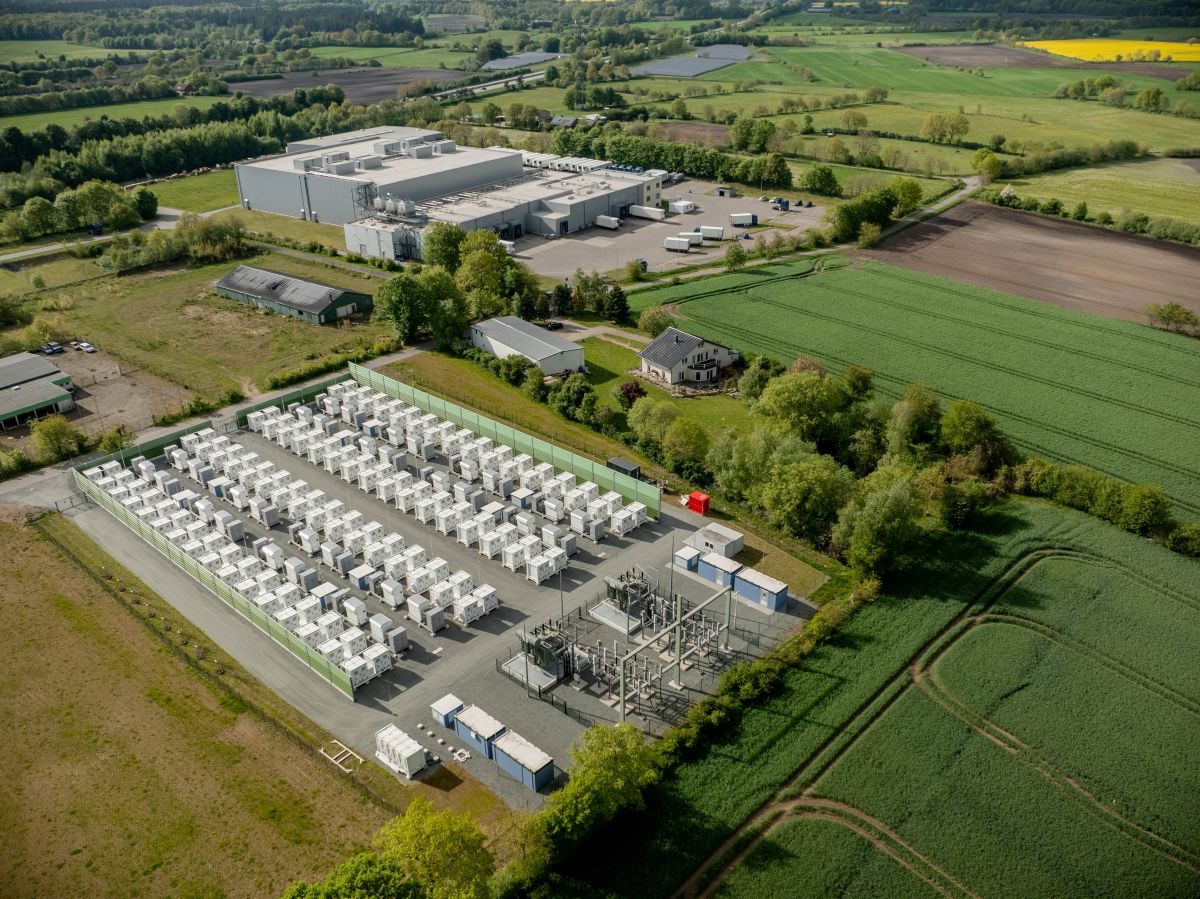
BESS, wind, and solar applications haven’t invented new failure mechanisms; they have simply accelerated the existing ones. Thermal aging, moisture migration, and mechanical fatigue now occur through a duty cycle that is faster, more frequent, and far less predictable than anything traditional transformers or switchgear were designed around. A Battery Energy Storage System depends on transformers, circuit breakers, switchgear, and controls all working together, which is exactly why you can’t protect what you can’t see.
The path forward is electrical asset intelligence built on integrated data: fiber optic hotspot visibility, smart cooling response, continuous moisture and RS sensing, true fault monitoring, multi gas online DGA, and condition-based switchgear analytics, all working together within a single asset management strategy rather than as disconnected point solutions.
If you’d like the full technical walkthrough behind these monitoring strategies, this article is based on our webinar, Monitoring Transformers in BESS, Wind, and Solar Applications, presented by Dr. Baba Das. Watch the full webinar here for the complete presentation.
Ready to build a monitoring strategy for the transformers and switchgear at your own BESS, wind, or solar sites? Contact us today and our team can set up a monitoring solution tailored to your needs.
Author: Katie Panke, Dynamic Ratings